
Page 23 - PHI - Cierrapuertas
P. 23
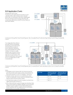
ELR Application Charts

          Simultaneous Pair of Doors                       115 / 230 VAC
          Pressing the push button retracts the latches on each                             ELR152
          exit device. When both exit devices have retracted   Battery                      Power
                                                                                            Supply
                                                           Backup
          latches, the control modules in the power supply signals   (Note 4)
          the door operators to open the doors. The doors will
          remain open until released by the Time Delay feature on   115 / 230 VAC          Door
          the Control Module.                                                              Operators
                                                                                           (Note 2)


                                                                                       Exit     Exit
                                                                                       Device   Device
                                                                                       (Note 3)  (Note 3)

                                                                              Push                          Push
                                                                              Button                        Button
                                                                              (Note 1)                      (Note 1)


          4 Conductor (28 Gage Min.) Power Transfer Required.  Ept-5 Concealed Power Transfer (See Page 29), Door Cord Or Hinge (Furnished By
          Others)


          Two Independent Pairs of Doors           115 / 230 VAC
          Each pair of doors are operated
          by pressing a push button which
          retracts latch(es) on each exit                                    ELR154
          device. When both exit devices                                     Power
                                                                             Supply
          have retracted latches the control             Door                                  Door
          modules in the power supply                    Operators                             Operators
                                                         (Note 2)
          signal the door operators (such as                                                   (Note 2)
          the Precision D-4990 Low Energy
          Operator) to open the doors. The   Push     Exit   Exit                          Exit    Exit     Push
                                            Button
                                                                                                            Button
          doors will remain open until released   (Note 1)  Device  Device                 Device  Device   (Note 1)
          by the Time Delay feature on the            (Note 3)  (Note 3)     Push          (Note 3)  (Note 3)
          Control Module.                                                    Button
                                                                             (Note 4)
                                                                         Push   Push
                                                                         Button  Button
                                                                         (Note 1)  (Note 1)
          4 Conductor (28 Gage Min.) Power Transfer Required. Ept-5 Concealed Power Transfer (See Page 29), Door Cord Or Hinge (Furnished By
          Others)
          Notes:
          1.  Push Button may be replaced with Card Reader, keypad,etc.,
            providing normally open contacts and/or voltage inputs. See   Wire Gage  Maximum Wire Run   Maximum Wire Run
                                                                                 for 22 Gage Power
            hookup instructions in the ELR150 Installation Instructions.         Transfer         for 28 Gage Power
                                                                                                  Transfer
          2.  Activation for Door Operators are provided by dry contact
            on the Control Module. (2) wires must be run from the Power   16     75’ – 0”         55’ – 0”
            Supply to each operator requiring control.          14               125’ – 0”        75’ – 0”
           3.  Each exit device requires (4) wires to operate. See chart to the   12  200’ – 0”   ---
            right for proper gage and wire run.
           4.  When Battery Backup is used, (2) 12 gage wires, less than 3 feet
            long, connect batteries to Backup. Batteries must be mounted
            outside the power supply enclosure. Battery Backup has a
            Power Tap feature that can provide power to a Card Reader,
            keypad system, etc. See page 22 for details.

                                                                             Apex 2000 Series Touchbar Exit Devices  23