
Page 26 - PHI - Cierrapuertas
P. 26
Delayed Egress Application Charts
Access Cover Feature – Mode Select Switch
panel can be accessed through a hinge
stile cover for ease of installation and
maintenance without removing the device
or Endcap Mounting Bracket. The access
cover is secured in place by the device
Endcap, which is attached with Security
Screws.
Mode Select Switches – The following
Mode Select Switch panel (see left) provides
field selectable settings to suit the various
Mode Select 5
Switches Delayed Egress applications.
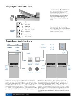
Delayed Egress Application Charts
120 VAC 3 x 14 GA. PS161-6 120 VAC 3 x 14 GA. PS161-6
Power Power
To Fire Alarm 2 x 18 GA. Supply To Fire Alarm 2 x 18 GA. Supply
2 x 18 GA.
2 x 18 GA. 2 x 18 GA.
2 x 18 GA. 2 x 18 GA. 2 x 18 GA.
2 x 18 GA. 2 x 18 GA.
Keypad, Card Keypad, Card
Reader, Etc. Reader, Etc.
DS880 DS880 DS880
Door Door
Position 2 x 18 GA. 2 x 18 GA. Position
Switch Switch
Remote Horn Remote Horn
Single Door – This application allows for remote Arm/Disarm and Double Door – This application allows for remote Arm/Disarm
remote monitoring of the Delayed Egress. The Exit device will delay and remote monitoring of the Delayed Egress. The Exit device will
egress when armed and will be a normal exit device when disarmed. delay egress when armed and will be a normal exit device when
The DS880 (DS) Door Position Switch (page 29) prohibits the door disarmed. The DS880 (DS) Door Position Switch (page 29) prohibits
from being held or forced open while the device is armed. The 24 the door from being held or forced open while the device is armed.
VDC, remote switch, remote horn and the DS are routed through the When one device is alarmed the other device will also go into alarm.
power transfer and the fire alarm is wired to the power supply. The 24 VDC, remote switch, remote horn and the DS are routed
through the power transfer and the fire alarm is wired to the power
supply.
26 Apex 2000 Series Touchbar Exit Devices