Page 8 - Cerraduras Best
P. 8

5E SERIES
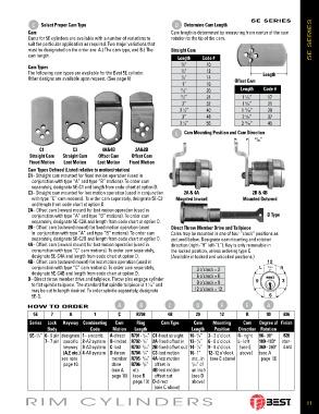
               C          Select Proper Cam Type                                Determine Cam Length
                                                                    D
            Cam                                                    Cam length is determined by measuring from center of the cam
            Cams for 5E cylinders are available with a number of variations to   rotation to the tip of the cam.        5E SERIES
            suit the particular application as required. Two major variations that
            must be designated on the order are: A.) The cam type, and B.) The   Straight Cam
            cam length.                                              Length    Code #

                                                                       5 ⁄8”    10
            Cam Types
            The following cam types are available for the Best 5E cylinder.  3 ⁄4”  12                Length
            Other designs are available upon request. (See page 8)     7 ⁄8”    14         Offset Cam
                                                                       1”       16
                                                                      11 ⁄4”    20           Length   Code #
                                                                      11 ⁄2”    24            1  ⁄16”   17
                                                                                               1
                                                                       2”       32            1  ⁄16”   21
                                                                                               5
                                                                      2  ⁄2”    40            1  ⁄16”   29
                                                                                               13
                                                                       1
                                                                       3”       48            2  ⁄16”   37
                                                                                               5
                                                                      3  ⁄2”    56            2  ⁄16”   45
                                                                                               13
                                                                       1
                                                                               Cam Mounting Position and Cam Di rec tion
                                                                    E
                                                                                                   11 ⁄32”
                C1           C3         4A&4B        2A&2B
            Straight Cam  Straight Cam  Offset Cam  Offset Cam
            Fixed Motion  Lost Motion  Lost Motion  Fixed Motion
            Cam Types Defined (Listed relative to motion/rotation)
            C1– Straight cam mounted for fixed motion operation (used in
             conjunction with type “A” and type “B” motions). To order cam
             separately, des ig nate 5E-C1 and length from code chart at option D.
            C3– Straight cam mounted for lost motion operation (used in conjunction   2A & 4A     2B & 4B
             with type “C” cam motions). To order cam separately, des ig nate 5E-C3   Mounted Inward  Mounted Outward
             and length from code chart at option D.
            2A– Offset cam (inward mount) for lost motion operation (used in
             conjunction with type “A” and type “B” motions). To order cam                              D Type
             separately, designate 5E-C2A and length from code chart at option D.
            2B– Offset cam (outward mount) for fixed motion operation (used   Direct Throw Member Drive and Tailpiece
             in  conjunction with type “A” and type “B” motions). To order cam   Cams may be mounted in one of four “clock” positions as
             separately, designate 5E-C2B and length from code chart at option D.  pictured below. Designate cam mounting and rotation
            4A– Offset cam (inward mount) for lost motion operation (used in    direction (right-“R” left-“L”). Key is only removable in
             conjunction with type “C” cam motions). To order cam sep a rate ly,    the locked position, unless ordering type C.
             designate 5E-C4A and length from code chart at option D.  (Available in locked and unlocked po si tions.)
            4B– Offset cam (outward mount) for lost motion operation (used in
             conjunction with type “C” cam motions). To order cam sep a rate ly,    3 o’clock = 3
             designate 5E-C4B and length from code chart at option D.        6 o’clock = 6
            D– Direct throw member drive and tailpiece. Throw pins engage cylinder
             to flat spindle tailpiece. The standard flat spin dle tailpiece is 1  ⁄16” and    9 o’clock = 9
                                                          1
             may be cut to length desired. To order spindle sep a rate ly, des ig nate   12 o’clock = 12
             5E-D.

            HOW TO ORDER                      A        B          C         D         E        E       A
              5E     7      A        1        C      R708        4B         20       12        R       90     626
            Series  Lock   Keyway Combinating   Cam   Ring     Cam Type    Cam     Mounting   Cam    Degree of  Finish
                   Body             Code    Motion   Length                Length  Position  Direction Rotation
             5E– /4” 6– 6 pin designate  1– uncomb.  A-direct  R701-  /16” C1-fixed straight  10-  /8”  3– 3 o’clock  R– right  90– 90°  626
                                                                             5
               3
                                                        1
                  7– 7 pin specific  2-A2 system B-limited R702-  /8” 2A-fixed offset in  12-  /4”  6– 6 o’clock  L– left   180–180°  stan-
                                                                             3
                                                        1
                         keyway  3-A3 system C-lost  R703-  /16” 2B-fixed offset out 14-  /8”  9– 9 o’clock  (see E   360– 360°  dard
                                                                             7
                                                        3
                         (A,E etc.) 4-A4 system D-throw  R704-  /4” C3-lost motion  16- 1”   12–12 o’clock  above)  (see A
                                                        1
                         see note           member  R705-  /16” 4A-lost motion   etc., in  (see E above)  page 10)
                                                        5
                         page 10.           drive   R706-  /8”  offset in  1 /16” of
                                                        3
                                            (see A   etc    4B-lost motion   an inch
                                            page 10)  (see B   offset out  (see D
                                                    page 10) D-direct      above)
                                                            (see C above)
           RIM CYLINDERS                                                                                               11
   3   4   5   6   7   8   9   10   11   12   13