
Page 4 - Cerraduras Best
P. 4
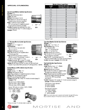
Mortise Cylinder Length Chart
SPECIAL CYLINDERS
1E SERIES Special Length Mortise Cylinders Spec i fi ca tions 1 ⁄8” “D”of order pro ce dure (page 2) Riveted cams
Length
Designate this number on step
“A”
22
3
24
1 ⁄2”
1
26
1 ⁄8”
5
Diameter: 1 ⁄32”
5
3
Uses: Special thickness doors
30
1 ⁄8”
Length: See chart 1 ⁄4” 28
7
Material: Solid brass or bronze 2” 32
Cam: Standard 1E-C4 cam (see page 2) 2 ⁄8” 34
1
supplied unless otherwise specified. 2 ⁄4” 36
1
Rings: The RP2 (for 6 pin) and RP3 2 ⁄2” 40
1
(for 7 pin) package are supplied standard “A”* 3
(page 2) unless otherwise specified. 2 ⁄4” 44
To order: Designate desired length from chart 1E74 3” 48 Screw-on cams
under length code step “D” as shown (page 2). 3 ⁄2” 56
1
Example: 1E-74-32 4” 64
4 ⁄2” 72
1
5” 80
5 ⁄4” 88
1
6” 96
*ONLY AP TO 1E74
1 ⁄2” Diameter Mortise Cylinder Spec i fi ca tions Taper Head Mortise Cylinder Spec i fi ca tions
1
Diameter: 1 ⁄2” Diameter: 1 ⁄32”
5
1
Length: 6 pin–1 ⁄8” ; 7 pin–1 ⁄4” Length: 6 pin – /32”; 7 pin – ⁄4”
23
1
1
3
Door thickness: Door thickness: 6 pin- 1 ⁄8” to
3
6 pin–1 ⁄8” to 2 ⁄4” (includes trim) 1 ⁄4” (including trim)
5
1
3
7 pin–1 ⁄8” to 2 ⁄2” 7 pin– 1 ⁄8” (including trim)
1
3
7
Material: Solid brass or bronze 7 pin– 1 ⁄4” (without trim)
3
Cam: Standard 3E-C3 cam supplied unless Material: Solid brass or bronze
otherwise specified. Cam: Standard 1E-C4 cam sup plied “A”*
Rings: The RP4 ring package is supplied unless otherwise spec i fied.
with 3E cylinders. This package includes a “A”* Rings: The RP1 ring package (page 2) is 1E76
3E-R2 ( ⁄8” ) and a 3E-R4 ( ⁄4” ) ring. supplied standard with all 1E taper cylinders (page 2).
1
1
To order: Designate “3E” on step “A” of order 3E74 To order: See page 2. Example: 1E-76-C181-626
procedure (page 2) Example: 3E-74-C3-RP4-626
Options: 3E-04-Dummy, 3E-7A4-Turn knob, 3E-7B4-Dust Cover. Turn Knob Cylinders Specifications
Adaptor ring to allow 1E74 cyl in ders to fit a 3E tapped hole - A26139. Diameter: 1 ⁄32”
5
Length: Mortise- 6 pin–1 ⁄8” ; 1EA6A4
1
Dummy Mortise and Rim Cylinders Specifications Rim- 6 pin–1 ⁄16” - 1EA6A2
3
Diameter: 1 ⁄32” Material: Solid brass or bronze
5
Length: Mortise –1 ⁄8”; Rim –1 ⁄8” Cam: Standard 1E-C140 cam supplied unless
1
1
Material: Solid brass or bronze oth er wise specified (see page 2).
Rings: Ring packages are supplied standard as follows: Rings: Ring packages are supplied standard
Mortise: RP2 ring package(see page 2) as follows (unless otherwise specified):
Rim: RP3 ring package (see page 3) Mortise 6 pin: RP2 ring package 1EA6A
To order: Designate “0” on step “B” of order procedure (page 2) (see page 2) *ADA Turn Knob Shown
Example: 1E-02 To order: Designate “A4” on step “C” of order procedure (page 2).
E04-slot in back-1ESPL-6-B4619 Example: 1EA-6A4-C140-RP3-626
1E04-slot in back-1ESPL-7-B4620 R-function turn knob cylinders
1E02-slot in face-1ESPL-6-A5035 RH-1ESPL-6-B35401
Special 1E04 with slot on back- 1ESPL-7-B4620 LH-1ESPL-6-B35405
Special length 1E04 cylinders: Special length cylinders
1 ⁄2” – 1ESPL-7-A9619 1.5”-1ESPL-6-A20336
1
1 ⁄4” – 1ESPL-7-A20331 1.75”-1ESPL-6- A20337
3
2”- 1ESPL-6-B23409
NOTE: These should not be used in con junc tion with deadbolt function BEST mortise
locks. To order the old style “UP” thumb turn contact your local BEST dealer.
1E04 12E02
* Reference to Length “A” on Mortise Cylinder Length Chart.
MORTISE AND
4