Page 7 - Cerraduras Best
P. 7

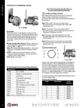
5E SERIES  UTILITY CYLINDER LOCK                                     Cam Motion and Degree of Rotation


                                                                      Refer To The Following Procedure When Ordering
                                                                        See Order Example At Bottom Of Next Page.

                                                                 A
                                                               When ordering 5E cylinders, specify the cam motion type and
                                                               degree of rotation. Available cam motion types are
                                                               listed below. Different type motions are limited to different degrees
                                                               of key rotations.
                                                               Type A– Direct motion - Key and cam rotation is direct.
                                                                 Key may be removed in locked position only. Motion is 360
                                                                 degrees right or left.
                             5E–  /4” Cylinder
                                3
                                                               Type B– Limited motion - Key and cam rotation is direct.
                                                                 Key may be removed in locked position only. Motion is limited to
           Specifications                                        90 degrees or 180 degrees right or left.
           The 5E utility cylinder lock fits standard  ⁄4” diameter cylinder
                                        3
           installations such as wood or metal desks,file cabinets, vending   Type C– Lost motion. Cam rotates 90 degrees right or left.
           machines, utility and storage cab i nets, elevators and security   Key rotates 360 degrees. Key removal with cam in locked or
           alarm control panels. The com plete 5E as sem bly includes a   unlocked position.
           combinated  ⁄4” cyl in der with cam, hex nut, lock washer and
                    3
           spacer collar.                                      Type D– Throw member drive - Key and drive motion is direct.
                                                                 Key may be removed in locked position only. Motion is 360
           Maximum mounting surface thickness– 5E utility  cylinder locks   degrees right or left.
            may be mounted on surfaces with the  following maximum
            thickness: 5E6–  ⁄16”, 5E7–  ⁄32”
                        11
                               27
           Keying– May be keyed individually, keyed alike or   masterkeyed   B Determine Ring Length
            into a new or existing Best standard  masterkeyed se cu ri ty
            system.
           Service– 5E cylinders may be recombinated and   serviced
            onsite. Special service equipment is   available (see Service   3 ⁄4”     7 ⁄8”
            Equipment Section of Best  catalog).
           Finish– 626 satin chrome only

                                                                                                   A     B
                                                               A spacer collar may be required to position the cam for proper lock
                                                               operation. The spacer collar is installed be tween the 5E cylinder
                                                               head and the mount ing sur face. To de ter mine the proper length of
           5E Combinating and Service Accessories Nomenclature Item  the spacer collar, add to geth er: the desired distance from the cam
                                                               to the inside of the mounting surface (“A” above) to the measured
             Nomenclature               Item                   thickness of the mounting surface (“B” above). Then, subtract this
                                                                       31
                                                                                              1
            A-8049        5E  /4” Hex Nut                      total from:   ⁄32”  when installing a 5E6, or 1  ⁄8” when installing a 5E7.
                            3
                                                               The remainder is the collar length, which is illustrated.
            A-21068       Washer for cylinder body head
            A-4845        Cam Screws                           To properly order spacer collars, designate the fol low ing no men cla-
            A-4045        Lock washer for cam screws           ture for the length desired:
                                                               5E Spacer Collar Length Chart
            5ED261        5E capping block                          Length       Nomenclature      To order
            5ED253        5E thread tap -  /4” x  #24                                              separately
                                     3
            5ED254        5E  /4” metal punch and die set (slab)
                            3
                                                                     1 ⁄16”          R701           5E-R701
            5ED262        5E cap depressor
                                                                     1 ⁄8”           R702           5E-R702
            5ECP6         Slide cap - 6 pin                          3 ⁄16”          R703           5E-R703
            5ECP7         Slide cap - 7 pin                            ⁄4”           R704           5E-R704
                                                                     1
            5ES1          5E springs                                 5 ⁄16”          R705           5E-R705
                                                                     3 ⁄8”           R706           5E-R706
           *NOTE: The 5E lock is not available for Premium and Peaks keying systems.
                                                                     7 ⁄16”          R707           5E-R707
                                                                     1               R708           5E-R708
                                                                      ⁄2


                                           MORTISE  AND
    10
   2   3   4   5   6   7   8   9   10   11   12