
Page 19 - Herrajes electricos Stanley
P. 19
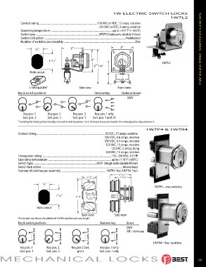
1W ELECTRIC SWITCH LOCKS
                                                                                                      1W7L2
             Contact rating  ............................................................................................110 VAC or VDC, 12 amps, resistive
                                                            220 VAC or VDC, 6 amps, resistive
             Operating temperature  ..................................................................................................up to +221°F (+105°C)
             Switch type  ....................................................................................................SPDT (Single pole-double throw)
             Switch lock action  ................................................................................................................................. Maintained
             Number of switches per assembly  .................................................................................................................One

                      7 /8”                                                                                              1W ELECTRIC SWITCH LOCKS


                              1  /32”
                               5
                                                                                                 1W7L2
                   Hole cutout


                  Limiting plate†               Side view              Front view
            Key & switch positions                       Remove key      Optional boxes
                                                                             SWR


               Key pos. 1     Key pos. 2     Key pos. 3  Key pos. 1 only
               Swt. pos. 1    Swt. pos. 2    Swt. pos. 1  Swt. pos. 1 and 2†
            † Installing the limiting plate limits key removal to switch position 1 or 2. The key is always removed in the vertical position (key position 1).

                                                                                        1W7P4 & 1W7R4
            Contact rating ..............................................................................................................30 VDC, 15 amps, resistive
                                                               125 VDC, 0.6 amps, resistive
                                                               250 VDC, 0.3 amps, resistive
                                                                125 VAC, 15 amps, resistive
                                                                   125 VAC, 5 amps, lamp
                                                                250 VAC, 15 amps, resistive
            Horsepower rating  ..............................................................................................................125–250 VAC, 1/2 HP
            Operating temperature  .................................................................................................... up to +176°F (+80°C)
            Switch type  ....................................................................................................SPDT (Single pole-double throw)
            Switch lock action  .................................................................................................................................Momentary
            Number of switches per assembly  .......................................................................1W7P4: Two 1W7R4: Four
                                                                         2   5   /16 "
                                                      1   1   /2 "        1   29   /32 "

                          7 /8”
                                                                                            1W7P4—two switches

                                  1  /32”      2   7   /8 "
                                   5

                       Hole cutout

                                                  Back view          Side view
            The shaded area shows the additional 1W7R4 switches and cam length.
            Key & switch positions                           Remove key     Boxes
                                                                            SWR
                                                                            INT (1W7P4 only)


                                                                                            1W7R4—four switches
             Key pos. 1      Key pos. 2     Key pos.3 Swt.   Key pos. 1 only
             Swt. pos. 1     Swt. pos. 2       pos.3        Swt. pos. 1 only

 IDH MAX  & ELECTROMECHANICAL LOCKS                                                                                    19
 ®